Watt a boat ...
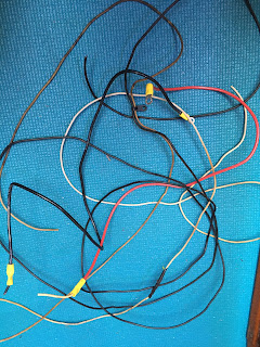
This is something I probably should have addressed sooner; namely, the electrical system. It’s kind of a mess which I guess is inevitable in a 35+ year old boat. The original bare-bones system has been added to and modified over the years so that now it’s a tangle of chaotic wiring with a schematic that makes little sense and some workmanship best described as ‘questionable’.
Yes, those are wire nuts you see buried in that rat’s nest (wire nuts should NEVER be used on a boat) but that is not the scariest thing I discovered.
When I did the pre-purchase survey, I was pleasantly surprised to see that the boat came with a functioning 1500W inverter; having access to AC power when away from the dock is always a nice option to have. When I started my investigation of this particular circuit, I noted that the inverter was hot-wired to the battery and happy to see a fairly short wire run of beefy one gauge cable connecting the two, meaning both the ampacity and the voltage drop of the circuit were more than acceptable. NOTE: One gauge SAE wire is a bit smaller than one gauge AWG wire, but it’s still plenty large enough to handle the inverter’s maximum constant current load of 125 amps.
What I was not happy about: neither positive nor negative cables were restrained correctly and both were routed through a single (ungrommeted) hole in a fiberglass bulkhead; and, after tracing the entire wire run, I couldn’t find any circuit protection! Here’s the potential nightmare: the positive and negative cables chafe on the edges of the hole, the insulation wears away, the positive cable grounds to the negative cable and sends a massive current surge through the cable which starts a fire and the boat burns to the waterline. This is not an optimal boating experience.
So, I installed an ANL fuseblock close to the battery with a 120A fuse, crimped on a couple of new connectors, drilled a new hole in the bulkhead, installed a grommet, separated the positive lead from the negative and secured all cables with clamps and tie locks. I feel much more comfortable now knowing that fire hazard has been eliminated, or at least severely mitigated.
While I was trying to make sense of the wire nest I saw a fairly large 6AWG cable coming off the positive bus block and then run to a fuseblock with a 100A fuse. The return ground cable was 8AWG (smaller than the positive lead) which was puzzling since 8AWG cable cannot safely handle 100 amps of current...click HERE to see why. What is going on here and what is this powering? First thing, I pulled out the 100A fuse and replaced it with a 40A fuse; now at least the fuse will blow before the wire starts melting! Next, I had to figure out where this cable ran to and what in the heck it powered, so I started tracing its path through the innards of the boat.
Eventually, I found the other end over by the nav desk. It terminated with a pigtail containing two small 18AWG wires. One powered a tiny LED desk lamp and the other a DC charging port which could conceivably draw five amps at most. What the heck!? Why are these large 6AWG/8AWG cables powering two very low load devices? My best guess is that the boat was once equipped with a smaller inverter and this was the power lead.
Since the boat already had this high capacity cable installed, I pulled apart the nav and radio station, re-routed these cables and connected them to a remote fuseblock which I installed under the nav desk and then wired all the devices at the nav desk (VHF radio, lights, CD/stereo, DC outlets) to this fuseblock. This will simplify things, allow me to rip out a bunch of wiring that runs cross-cabin, eliminate a number of separate fuse holders, allow for future expansion and overall just make the electrical system a more elegant design.
Yet another uncomfortable discovery: there is no breaker on the boat for the AC shorepower circuit. Although not required, I installed an ELCI breaker up in the V-berth; this will keep it within 10 feet of the shorepower cord receptacle which is located in the anchor locker and prevent my boat from becoming the reason for another ESD fatality. I mounted it (and an AC outlet) in a cover box I made out of scrap mahogany from Bill’s shop similar to the one already installed that covers the potable water inlet hose.
To view the spreadsheet I used to organize the electrical system, click on the link below:


