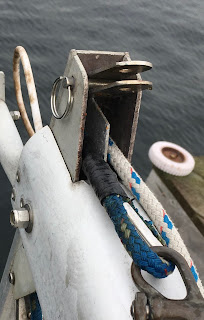
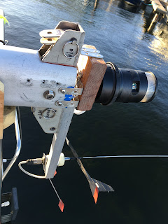
Mast projects ...
With the mast down, now is the time to complete the project list I’ve been compiling ever since I got the boat; some things are repairs and others are modifications needed for the final square-rigged configuration.
HALYARD SHEAVES
I noticed the first time I raised the mainsail that the halyard had excessive resistance which seemed to originate at the masthead. Once the mast was down, I fully expected to find one or more of the halyard sheaves broken apart or missing, and the halyard riding on the hinge pins. Instead, once I removed the sheave box from the masthead, I discovered four intact sheaves, but sheaves that were way undersized; properly sized sheaves for 3/8” line should be about 3” diameter, but the existing sheaves were only 1” diameter. Due to dimensional limitations of the masthead sheave box, the largest replacement sheaves I could use were 2” diameter. Here are the old sheaves and new sheaves for comparison purposes:
Locating and drilling the holes for the sheave pins was a bit tricky: Too high and the halyards running on top of the sheave would rub on the underside of the sheave box; too low and the sheave edges would rub on the bottom of the box; too far forward (or aft) and the sheaves would interfere with the bolt that holds the sheave box to the masthead; too far aft (or forward) and the halyards would exit the box at an improper angle. I also had to ensure proper edge distance from the existing holes in the sheave box.
BASEPLATE
I had noticed small cracks around the fixture that holds the base of the mast in place. I removed this fixture (which required cutting into the salon’s headliner to access the nuts) and found more cracks hidden underneath the baseplate. I ground out the cracks with my Dremel tool and filled in the repair with epoxy paste. Once the epoxy had fully cured, I sanded the repair flush with the deck and then reinstalled the baseplate.
Thankfully, none of the cracks extended deeper than the gelcoat so the underlying fiberglass was structurally sound, but I wanted to know WHY the cracks developed in the first place. I had assumed the compression post in the cabin was centered under the baseplate, but when I removed the headliner, I discovered this was not the case; the compression post is actually offset a couple inches to port and NOT centered under the baseplate. My guess is that when the mast is really loaded up under compression, this slight asymmetry is enough (over time) to create these cracks.
To remedy the situation and hopefully prevent further cracking, I added a 3/4 inch extension to the starboard side of the compression post. This will increase and center the bearing surface of the compression post but still allow access to the baseplate fasteners. I also replaced the old fasteners with new stainless steel machine screws, locknuts and larger, beefier washers since the old washers were deformed from prior mast loads.
YARD-SPAR TRAVELER T-TRACK
Currently, the yard-spar cannot be raised higher than the spreaders due to the mast retention loop. I intend to replace this retention loop system with a traveler, running on T-track that is mounted on the front of the mast. The center of the yard-spar will be connected to this traveler which will allow the yard-spar to slide above the spreaders while still being secured to the mast. Think of it as a really long (18 feet) main sheet traveler that is vertically mounted.
I purchased three 6-foot sections of 1.25” wide aluminum T-track; the track is attached to the mast every 4” with 1/4” stainless steel machine screws. It’s critical where the sections meet that they are exactly aligned; just being off 1/32 of an inch will cause the traveler to catch on the gap. My nightmare is having the traveler (and 20 pound yard-spar) hang up halfway up the mast and having no way of getting it down.
To ensure each section is exactly aligned with the adjacent section, I fabricated a custom bushing out of an aluminum 5/16” roll pin. I reamed the inner diameter of the pin out so the drill bit for my 1/4” tap fits tightly inside. The outer diameter of the pin fits tightly inside the attachment holes for the T-track, so now I can insert the pin into each T-track hole and confidently drill away; the bushing ensures the bit stays centered in the hole.
The bushing did wear down after a few holes, so I had to make a few extra, but it worked great; each section aligns perfectly and the traveler runs smoothly along the entire 18 feet of T-track. I attached the two upper (high load) sections using Loctite on the fasteners and on the bottom (low load) section will use anti-seize compound since it may need to be removed someday. Drilling and tapping 50 holes is an all day endeavor!
LIGHTING
The boat came with an inoperable anchor light at the masthead and a steaming light mounted on the front of the mast, just above the spreaders. Once I got the mast down, I was able to get the anchor light working, but instead of a nice bright white light, it was a dim purple! Cool and psychedelic perhaps, but not legal and certainly not functional. Either the light itself was faulty or perhaps the voltage reaching the light was low due to the long run of 18 gauge wire. The steaming light worked, but it needed to be either moved up the mast or removed to make way for the yard-spar T-track (see above).
In the end, I decided to remove both of these lights and replace them with an LED combo light that serves both purposes. Once I had removed the two existing fixtures, I snaked a new cable that contains three 14 gauge wires (to keep voltage drop below 3%) through the mast using the existing cable. One wire will be a common ground for both lights, one will be the power lead for the anchor light (360 degree illumination) and the last wire will power the steaming light (225 degree illumination). I also included a line which can be used for future wire runs through the mast.
I fabricated a mounting base for the new fixture out of mahogany which I then epoxied for protection from the elements.
I attached the base plate to the masthead with some modified stainless steel L-brackets; this required tapping some new holes for the #10 machine screw fasteners. Here is the completed installation:
RUNNING BACKSTAY
Now that I’ll be able to hoist the yard-spar above spreader level, I need a way to counteract the force the head of the square sail will impart to the mast and minimize (or even eliminate) the induced bending moment. [For a detailed explanation, see the design document, PROPOSED CONFIGURATION #5 ... click HERE]
I spliced some 1/4” Dyneema to a couple of cheeky tangs (from Colligo) and mounted these on the mast where the yard-spar will typically be raised.
I spliced a thimble onto the other end of these running backstays. These will be lashed to D-rings mounted securely on the outer edge of the cockpit coaming and the lashings secured to nearby cleats. When not in use, the lashings can be easily removed and the running backstays stored and secured at the base of the mast. [NOTE: they can also be used as “running lazyjacks”]
SPREADERS
In order to move the upper shrouds to the aft chainplate (to allow greater rotation of the yard-spar) the spreaders need to rotate aft about 25 degrees. I had previously done a rough job of removing some material from the aft edge of each spreader to allow this to happen, but now that the mast was down, I could do it properly. I unbolted each spreader from its attachment bracket and used my Dremel tool to smooth away enough material to allow the spreaders to move aft the correct amount. I also added some retention screws to each bracket to keep them from rotating when the spreaders are aft.
MISCELLANEOUS
The old spreader boots were removed, the spreader ends inspected, and new boots installed with multiple wraps of rigging tape. This required moving the small blocks used for signal/flag hoists inboard a few inches to ensure a proper fit.
Spacer blocks were installed below the lower shroud attachment fittings in case I need to revert back to using the mast retention loop when raising the yard-spar:


